Whether you are new to the industry or are well seasoned and want to review some of the basic information that you learned in the past, these courses and lessons will clearly outline what you are looking for. “Power Systems Electric” is On-Line training that bridges the gaps between textbook theories and practical power systems experience. As a retired electrical engineer who has gone through the experience of developing a career in electrical power systems, I know how frustrating it can be to try and find the answers, so I put together these courses that I feel would have been a major help to me in my development. I have also taken suggestions from students of what they would like to see in addition to these courses which I have given live in person.
Basic Electrical Learning
For those new to the industry, there is a beginner’s group of courses that cover the “Fundamentals of Electricity” including DC and AC Circuit Analysis. These lessons examine such basics as Ohm’s Law, Series, and Parallel Circuits. The first, and perhaps most important, relationship between current, voltage, and impedance, “Ohm’s Law”, and its relevance to Series and Parallel Circuits. Subsequently, this will lead to the development of Kirchhoff’s Laws as they help to further analyze Network Analysis & Metering Circuits.
Conductors and Insulators are investigated along with their connected components, Capacitors, Inductors, and how they are influenced by Electromagnetism.
Alternating Current (AC – an electric current that periodically reverses direction) is the form in which electric power is delivered to businesses and residences, and it is the form of electrical energy that consumers typically use when they plug kitchen appliances, televisions, fans, and electric lamps into a wall socket.
The abbreviations AC and DC are often used to mean simply alternating and direct, as they are applied to current or voltage.
These AC courses deal specifically with sinusoidal waveforms and will provide the student with the basic understanding of working with circuits involving Alternating Current, which includes sinusoidal waveforms, vectors & phasors, reactance & impedance of R,L,C circuits, as they relate to the basic laws and theorems of electricity. This includes working with AC Power, Power Factor, Resonance, Complex Numbers, Reactance, and Impedance
Advanced Electrical Learning
These Courses involve subjects such as “Short Circuit Analysis for HV Three-Phase Systems” which introduces the student to the basic concepts of fault studies on a high voltage three-phase system. System modeling is then used in order to aid in this process, with the ability to move between asymmetrical and symmetrical systems. With hey Searle and extensive study of “Per Phase” & “Per Unit” methodologies system faults are analyzed with the use of symmetrical components.
“A Per-Unit System” is the expression of system quantities as fractions of a defined base unit quantity. Calculations are simplified because quantities expressed as per unit do not change when they are referred from one side of a transformer to the other.
In these courses, you will learn exactly what Per Unit Analysis is, the main advantages of using it, how manufacturers of equipment use and rate their products, and the technique of converting to and from the Per Unit system.
Several examples of working with Per Unit are demonstrated in this crisp clear presentation. When you finish you will have a though understanding of this subject.
It is important for all power engineers and technicians to be familiar with the concept of Per Unit as it is being used and referred to every day in power flow, short circuit evaluation, and motor starting studies.
The method of “Symmetrical Components” is used to simplify asymmetrical three-phase voltages and current analysis by converting the unbalanced system into two sets of balanced phasors and a set of single-phase phasors, or symmetrical components. These sets of phasors are called the positive, negative, and zero sequence components.
An understanding of this method is essential for the understanding of fault analysis and modern-day protection schemes. These courses will provide you with the knowledge to comprehend the concept and how it is applied.
Supplemental Electrical Lessons
In all power electrical analyses, the student will encounter special Trigonometric and Mathematical identities and equations. This site contains special supplemental lessons that zero in on those identities and equations. For example, there are lessons that take you from the “Fundamentals of Trigonometry” to the more sophisticated requirements in electrical engineering. As you work and study in electrical engineering you are going to run into proofs and equations that are based on trigonometry. A good example of this is when studying AC current, voltage, and impedance calculations, phasors or vectors are used and combined mathematically. Further adventures into complex power will also require a knowledge of trig functions and identities. As a student of this course, you will be introduced to these or at least re-introduced to these that may have been long since forgotten.
In mathematics, “The Derivative of a Function” of a real variable measures the sensitivity to change of the function value (output value) with respect to a change in its argument (input value). Derivatives are a fundamental tool of calculus. For example, the derivative of the position of a moving object with respect to time is the object’s velocity: this measures how quickly the position of the object changes when time advances.
Specialized Electrical Lessons
Specialized lessons include the “Protection & Control(P & C)” principles of high voltage stations. HV Bus Differential Protection is studied along with restrictions due to CT saturation & mismatch and its solution, “Restraint Differential Protection”.
High Voltage Circuit Breakers are examined as to the various Types (Oil, Vacuum, Air Blast, SF6), their Controls as well as the introduction of potential transformers & current transformers, and their use in conjunction with the relevant instruments such as ammeters, voltmeters, watt meters, and energy meters.
Other lessons include the study of “Transformers” including core construction along with losses, cooling, and mitigation techniques. Three-phase transformer configurations are studied along with harmonic distortion, CT saturation, and on-load tap-changer problems and how these problems are dealt with. Over-current and restraint differential transformer protection is developed along with a look at some examples of ” Old School relays” as well as modern IDE (intelligent Electrical Devices) relays.
Transformer Connections: (Y – Y; Delta – Delta; Y – Delta; Delta – Y & Y – Zag Zig) are examined along with Transformer Clock System Vector Nomenclature.
Lastly, there is a special section dedicated to “Single and Three-Phase Metering“, including old analog and new digital kilowatt-hour meters.
Conclusion
Regardless of whether or not you are new to the industrial power system, you’ll find what you’re looking for on this site in the way of training. In order to review or select any of these courses, left-click on any of the blue highlighted hyperlinked words of this posting or on “14 Courses Available” from the top menu of the landing page. All of the courses have a free introduction

As a bonus and in the way of a thank you, for your interest in PSPT’s WEB (and Blog) page, I’m making available my 50-page “Electrical Power” crib sheets. These were prepared for use with my courses that are available on this site. There is one section associated with each course and is extremely valuable while viewing the course, as well as a recall of the pertinent formulas and information after the fact. The contained information is also useful during any technical career as a quick reference from time to time. Simply click here or on the picture to the right to be taken to where you can download this item.


Blog #58 - Find Two Sets of Practice Problems in my Stand Store
/
As promise I have now loaded two sets of practice problems in my stand store. You can access them by going to this web address…https://stan.store/GVB

At this web address you will also find a collection of electrical related courses from the entry-level to the more advanced. The newly added problem sets may be found at the bottom of the listings.

Remember, this video has been brought to you by PSPT, where you will find electrical train training videos when you go to this web address…https://bit.ly/47YB3vh… which will also give you a free copy of my 50 page crib sheets that you can use while viewing any of the courses or just keep handy during your every day work.
Blog #58 - Calculating Current Using The Superposition Theorem
/
As part of my problem series in this video, I will be Calculating Current Using The Superposition Theorem.
Once I am finished with this series of problems I will be posting them in my Stan store, https://stan.store/GVB

In applying superposition to this problem, we consider each source acting alone.
3) If we zero the current source, i.e., replace it with an open circuit, now shown…
2) this circuit only gives us part of the answer as to what V0 is…let’s call it V0’
1) Using voltage division to find V0’…
If we zero the voltage source, i.e., replacing it with an short circuit…
I am also rearranging the circuit slightly that will allow us to analyze it a little bit easier. Again this circuit only gives us part of the answer as to what V0 is let’s call it V0’’ in order to find out what the V0” is we first must find the current that would be flowing in the 4Ω resistor. We will call that current IX…Using current division to find IX…which is this now V0” can be calculated using ohms law…which gives us…And finally…
V0 = V0′+ V0”…substituting for V0′and V0”…adding the two fractions we get…5.42 ∠4.57° and (5.4 + j0.4) Volts…in both polar and rectangular coordinates… which should not be a big surprise since that's what we found when we used loop analysis.

I want to introduce you to another product that’s out there that is worthy of paying attention to. The Anker SOLIX F2000 Generator.
To find out more about this battery generator and to keep up-to-date on any sales or discounts are available simply go to the anchor site at this web address…https://shrsl.com/4pplo… And by using this web address you can get $800 off the original price…. Or just browse through the various options on this site… There is no charge for just looking but you might find something that is available at a discounted price at this particular time.

For more information on other manufactures of battery back up systems here are some of the suppliers of solar equipment.
➜ EcoFlow at this address https://bit.ly/standy_power
➜ Bluetti at at this address https://bit.ly/4fDx2Ba
➜ Jackery at this address https://bit.ly/3YCiw5Y

Remember, this video has been brought to you by PSPT, where you will find electrical train training videos when you go to this web address…https://bit.ly/47YB3vh… which will also give you a free copy of my 50 page crib sheets that you can use while viewing any of the courses or just keep handy during your every day work.
Blog #57 - Government Rebates for Solar Equipment
/
The province of Ontario has just released a $5,000 rebate to install solar panels.
The program is called the Home Renovation Saving Program and it begins January 28th, 2025. One of the best parts about this program is that unlike the Federal Greener Homes grant that require that homeowners get a home energy assessment in order to qualify, this program is not going to require that assessment.
So, less hoops to jump through and easier to get the money for homeowners. The other thing to mention is that in addition to $5,000 towards the cost of solar panels, they're also offering an additional $5,000 towards batteries.

To register for the Ontario Solar Rebate Program, you can follow these steps:
For the Initial Registration…After January 28th, 2025, visit the official Ontario Energy Rebates website at (https://ontarioenergyrebates.com)…to begin the process then
Get a home energy assessment with a Registered Energy Advisor and
Receive a custom report with upgrade recommendations

You can then follow this recommended Process…
Find a qualified solar installer who can help guide you through the application at this WEB address…https://ontario-solar-installers.ca/
Complete an initial EnerGuide evaluation by a registered energy advisor
The advisor will assess your home's energy use and provide recommendations for solar panel installation

The key details of the program are:
➜ You can receive up to $5,000 in solar panel rebates.
➜ The program is available until 2027 and…
➜ Eligible properties include residential homes, small businesses, and farms.

There are similar solar incentive programs available to residents of the United States. The federal government and many states offer various incentives to promote solar energy adoption.

For more information on the solar programs as they happen, stay tuned to my videos, which will be updated regularly, in the meantime here are some of the suppliers of solar equipment.
➜ EcoFlow at this address…https://bit.ly/standy_power
➜ Bluetti at…https://bit.ly/4fDx2Ba
➜ Anker at, and, lastly…https://shrsl.com/4pplo
➜ Jackery at this address…https://bit.ly/3YCiw5Y
Blog #56 - Calculating the Voltage Vo Using Loop Analysis
/
As part of my problem series in this video, I will be Calculating the voltage V0 Using Loop analysis.
Once I am finished with this series of problems I will be posting them in my Stan store, at this web address…https://stan.store/GVB

Find V0 in this network using Loop analysis.
Since the network has two loops, or two meshes, we will need two equations to determine all the currents.
Note that since I2 goes directly through the current source, I2 must be 2∠0°A. therefore, one of our two equations is ready solved and…
I2 = 2∠0°…If we now apply KVL to the loop #1, we obtain…
−12 + I1through and times the two impedances (2 − j1) and since for the next two impedances the current will be the sum of (I1 - I2) so we must add the product of (I1 − I2) times (4 + j2) = 0…We now have two equations which will yield the mathematical solutions for the two currents….
Substituting for I2 from the first equation into the second now leaves us with one equation and one unknown, I1…removing the brackets yields…
-12 + 2I1 - jI1 + 4I1 - 8 + j2I1 - j4 = 0… I have coloured the I1 terms for clarity and collecting like terms moving the whole numbers to the right of the equation and keeping the variable on the left we get…I1(6 + j1) = 20 + j4…cross multiplying…which is the same as dividing both sides of the equation by (6 + J1)…

we get I1 = (20 + j4)/(6 + j1) or I1 is = 3.35∠1.85° A or (3.3 + j0.1) Amps…in both polar and rectangular coordinates. The voltage drop across the 4kΩ is V0 which is equal to 4(I1 − I2)… substituting our known values for the two currents…
V0 = 4 times I1 which we know is 3.35∠1.85° minus I2 which we know is 2∠0°)… converting to rectangular coordinates in order to perform the addition = 4 times 3.3 + j0.1 minus…2 @ 0° in rectangular coordinates is just 2 + j0.0… adding the two current results in…= 4(1.3 + j0.1)… finalizing the arithmetic the voltage is equal to…
= 5.2 + j0.4 Volts and 5.42∠4.57° Volts…in both polar and rectangular coordinates.

I want to introduce you to another product that’s out there that is worthy of paying attention to. The Anker SOLIX F2000 Generator.
To find out more about this battery generator and to keep up-to-date on any sales or discounts are available simply go to the anchor site at this web address… And by using this web address…https://shrsl.com/4pplo…you can get $800 off the original price…. Or just browse through the various options on this site… There is no charge for just looking but you might find something that is available at a discounted price at this particular time.

Remember, this video has been brought to you by PSPT, where you will find electrical train training videos when you go to this web address…https://bit.ly/47YB3vh…which will also give you a free copy of my 50 page crib sheets that you can use while viewing any of the courses or just keep handy during your every day work.
Blog #55 - Calculating Current and Impedances of this Parallel RLC Circuit
/
As part of my problem series, in this video, I will be Calculating the current and impedances of this parallel RLC circuit…
Once I am finished with this series of problems I will be posting them in my Stan store, at this web address…https://stan.store/GVB
Calculate the impedance of this parallel RLC circuit and the Currents in R, L, and C
The Angular frequency is given by ω = 2πf plugging in actual values we get (2)(3.1416)(60 Hz) = 377 rad/sec
XC = -1/(ωC) = -1/[377)(26.5)x10-6] = -100 Ω

XL = ωL therefore, XL = (377)(0.5) = 188.5 Ω
We will use the voltage as a reference again; therefore E = 200 ∠0 deg V…its phasor shown here in blue…
From Ohm’s law the current in the resistor is IR and that is equal to E/R or 200 ∠0 deg/100 ∠0 deg = 2 ∠0 deg Amps…its phasor shown here in red…
From Ohm’s law: IL = E/XL = 200∠0 deg/188.5∠90 deg = -j1.06 Amps…its phasor shown here in red…1.06 Amps at -90°
From Ohm’s law: IC = E/XC = 200∠0 deg/100∠-90 deg = +j2.0 A…its phasor shown here in red…2 Amps at +90°
Again note: that in my diagram, the magnitudes of the phasors are not necessarily exactly to scale. They were meant for demonstration purposes only.

IT is the vector sum of 2 + j2 - j1.06 = 2 + j0.94 = 2.21@25.2 deg A
Adding the vectors…we start with the current IR which is 2 A… And add to it the current in the capacitor which is…
IC 2 @ + 90°And add to it the current in the inductor which is…
IL -1.06 @ - 90°…so summing the phasors or vectors we get…
IT = 2 +j0.94 or 2.21∠25.2o Amps.
Impedance is ZEQ = E/IT = (200∠0 deg)/2.21∠25.2deg = 90.5 ∠-25.2deg Ω.

So we calculated the impedance of this parallel RLC circuit and the Currents in R, L, and C…and were done!

You'll find these problem-solving skills come in handy when automating your home, using Z-Wave products such as these lighting switches that are extremely versatile. With them you can create a mood, accented by the lighting…
Mood Lighting is Easy. Let's set the scene for movie night or a romantic dinner!
With Z-Wave light switches and bulbs connected to your Z-Box Hub, creating the perfect ambiance is just a tap away. Dim the lights, change colors, or set up automated scenes. Movie night? Dinner party? Your hub's got you covered!
For many, smart light switches are the first thing that come to mind when considering the benefits of home automation. Controlling your lights is one task that you are certainly willing to delegate to a smart assistant to automate scheduled events, respond to activities in your house, and even support your verbal commands.
Browse the wide selection of Z-Wave switches and lighting control options.
Not all Z-Wave light switches are compatible with your Z-Wave hub so they've made it easy for you to shop by selecting your hub model to find the switches and dimmers that will integrate well with your z-wave network. Z-wave switches are the ones you can control your home lighting from your smart phone, Alexa, or Z-wave controller interface. The configuration options for your lighting are endless. Find the best prices online at this WEB address…https://tinyurl.com/thesmartesthouse

If you are ready to elevate your living space with home automation, now’s the perfect time to transform your home into a smart, efficient household! In order to explore an incredible range of innovative products that cater to all your smart home needs.
Simply go to this website…https://tinyurl.com/thesmartesthouse
Don’t miss out on exclusive discounts available for a limited time! Take the first step towards a smarter home and discover how easy it is to enhance your lifestyle with cutting-edge technology. Your dream home awaits!

Remember, this video has been brought to you by PSPT, where you will find electrical train training videos when you go to this web address…https://bit.ly/47YB3vh...which will also give you a free copy of my 50 page crib sheets that you can use while viewing any of the courses or just keep handy during your every day work.
Blog #54 - The Smart Home Z-Wave Z box hub - some examples
/
In today's video we are going to continue to look at the Z box hub. In order to tune in to the complexity and technology of the Z box hub, you might want to visit my Stan store and brush up on some of your basic electrical information formulas and theorems at this web address…https://stan.store/GVB

Hey smart home enthusiasts! It's time to take your Z-Wave game to the next level with the Z-Box Hub! I'm excited to show you some awesome examples of how this little powerhouse can transform your home. Let's dive into a few scenarios that'll make you wonder how you ever lived without it!

For your secure and Smart Entry…Picture this: You're approaching your front door, arms full of groceries. No need to fumble for keys! Imagine your Z-Box Hub paired with a Z-Wave smart lock. Your thumb automatically unlocks the door. No more juggling bags or searching for keys! Plus, you can check lock status and even grant access to guests remotely. It's convenience and security rolled into one!

For perfect climate control who doesn't want to come home to the perfect temperature?
Connect your Z-Wave thermostat to the Z-Box Hub and take control of your home's climate like never before. Set schedules, adjust temps remotely, or let the hub learn your preferences. It's energy efficiency and comfort working in harmony!

Mood Lighting Made Easy. Let's set the scene for movie night or a romantic dinner!
With Z-Wave light switches and bulbs connected to your Z-Box Hub, creating the perfect ambiance is just a tap away. Dim the lights, change colors, or set up automated scenes. Movie night? Dinner party? Your hub's got you covered!
For many, smart light switches are the first thing that come to mind when considering the benefits of home automation. Controlling your lights is one task that you are certainly willing to delegate to a smart assistant to automate scheduled events, respond to activities in your house, and even support your verbal commands. Browse the wide selection of Z-Wave switches and lighting control options.
Not all Z-Wave light switches are compatible with your Z-Wave hub so they've made it easy for you to shop by selecting your hub model to find the switches and dimmers that will integrate well with your z-wave network. Z-wave switches are the ones you can control your home lighting from your smart phone, Alexa, or Z-wave controller interface. The configuration options for your lighting are endless. Find the best prices online at this WEB address….https://tinyurl.com/thesmartesthouse

Mood Lighting Made Easy. Let's set the scene for movie night or a romantic dinner!
With Z-Wave light switches and bulbs connected to your Z-Box Hub, creating the perfect ambiance is just a tap away. Dim the lights, change colors, or set up automated scenes. Movie night? Dinner party? Your hub's got you covered!
For many, smart light switches are the first thing that come to mind when considering the benefits of home automation. Controlling your lights is one task that you are certainly willing to delegate to a smart assistant to automate scheduled events, respond to activities in your house, and even support your verbal commands. Browse the wide selection of Z-Wave switches and lighting control options.
Not all Z-Wave light switches are compatible with your Z-Wave hub so they've made it easy for you to shop by selecting your hub model to find the switches and dimmers that will integrate well with your z-wave network. Z-wave switches are the ones you can control your home lighting from your smart phone, Alexa, or Z-wave controller interface. The configuration options for your lighting are endless. Find the best prices online at this with address…https://tinyurl.com/thesmartesthouse

If you are ready to elevate your living space with home automation, now’s the perfect time to transform your home into a smart, efficient household! In order to explore an incredible range of innovative products that cater to all your smart home needs.
Simply this website…https://tinyurl.com/thesmartesthouse
Don’t miss out on exclusive discounts available for a limited time! Take the first step towards a smarter home and discover how easy it is to enhance your lifestyle with cutting-edge technology. Your dream home awaits!

Remember, this video has been brought to you by PSPT, where you will find electrical train training videos when you go to this web address…https://bit.ly/47YB3vho give you a free copy of my 50 page crib sheets that you can use while viewing any of the courses or just keep handy during your every day work.
Blog #53 - Impedance Problem
/
Welcome again to a transformative journey through the world of electricity! As your guide, I'm excited to present a comprehensive suite of courses designed to illuminate the path from novice to expert. Let's explore how these courses can spark your potential and energize your career.

Our Model Bridges the gaps in electrical education, from curious beginners just starting out to seasoned professionals seeking a refresher. We're not just offering courses; we're providing a scalable solution to empower your electrical journey.

In this problem we are too calculate the current in this circuit for that we need to know the total impedance of the circuit. The angular frequency is given in hertz or cycles per second but we needed in radians per second so converting it…the angular frequency ω = 2π times the frequency in Hz f or…(2)(3.1416)(60)… which is 377 rad/sec.
∴ XL is equal to ωL…is (377)(0.5) = 188.5 Ω…and XC = minus 1/(ωC)… plugging in our actual values - 1/[377)(26.5)x10-6] which is = - 100 Ω.
Let’s let the total reactive impedance of the circuit be XT which is XL plus XE…
Then Z = R + j(XL - XC) = R + jXT 100 - j88.5 in the rectangular coordinate format… or in polar coordinate format…Z = 133.5 @41.5° Ω
The impedance triangle here illustrates the results of the preceding solution.
From Ohm’s law for AC circuits, the current I can be described by the applied voltage E divided by the circuit impedance Z all of these of course are phasors…
I am letting the source voltage E be reference here so 120 Volts at 0 degrees looks like this…and the impedance Z being equal to 133.5∠41.5 deg. Therefore the current I = 120∠0 deg/133.5∠41.5 deg…or .899∠-41.5 Volts…which looks like the above…
Which means the current will be lagging the reference voltage by 41.5 deg.
Note: in my diagram, in order to fit the phasors comfortably on the slide, the magnitude of the current is exaggerated compared to the voltage, however the angles are correct.

Here is why you should choose us…
➜ Expert-led instruction
➜ Flexible learning paths
➜ Real-world applications
➜ our courses are Highly Rated

Visit our Stan Store www.stan.store/GVB to explore our full range of courses and start your journey today. Remember, in the world of electricity, knowledge is more than power – it's the key to a brighter future.
Thank you for joining me on this electrifying journey. Let's power up your potential together!
Blog #52 - Electrical Courses in my Stan Store
/
Welcome to a transformative journey through the world of electricity! As your guide, I'm excited to present a comprehensive suite of courses designed to illuminate the path from novice to expert. Let's explore how these courses can spark your potential and energize your career.

Our Model Bridges the gaps in electrical education, from curious beginners just starting out to seasoned professionals seeking a refresher. We're not just offering courses; we're providing a scalable solution to empower your electrical journey.

Whether you're taking your first steps into the world of electricity or you're an experienced engineer looking to revisit fundamental concepts, we have the perfect course for you. Let's address the challenges that keep you up at night and turn them into opportunities for growth.

We understand the complexities you face in the electrical field. Our courses are meticulously crafted to not only solve your immediate problems but to equip you with the knowledge to tackle future challenges with confidence.

Our Choice of Media: Engages with our content across multiple platforms TikTok, Instagram, YouTube, and more including a stand store. We're bringing the knowledge directly to you, making learning accessible and convenient.

We're continuously building our Machine: a robust system to ensure your learning experience is smooth and effective. As we grow, we're committed to maintaining the quality and personalization that sets us apart.

In order to showcase an example…this is a sample taken from my course “Basic Fundamentals of DC Circuit Analysis” - Chapter 6 Series & Parallel Circuits. Here we are looking at a series circuit highlighting the fact that the current is the same in all of the components and in this case is 0.5 mA.

Because the current is 0.5 mA then the 0.5 mA will flow through each resistor and a voltage drop will appear across each resistor. The voltage drops across each resistor, will be given by Ohm’s law for R1, for R2 and for R3.
Notice the sum of the voltage drops (1.5 +5 + 2.5) is equal to the battery (supply) voltage:
9 volts.
This is a principle of series circuits: that the supply voltage is equal to the sum of the individual voltage drops.

Here is why you should choose us…
➜ Expert-led instruction
➜ Flexible learning paths
➜ Real-world applications
➜ our courses are Highly Rated

Visit our Stan Store www.stan.store/GVB to explore our full range of courses and start your journey today. Remember, in the world of electricity, knowledge is more than power – it's the key to a brighter future.
Thank you for joining me on this electrifying journey. Let's power up your potential together!
Blog #51 - The Smart Home Z-Wave products…The Z box hub
/
In today's blog we are going to look at one of the Smart Home Z-Wave products… The Z box hub in order to tune in to the complexity and technology of the Z box hub, you might want to visit my Stan store to brush up on some of your basic electrical information formulas and theorems at this web address…https://stan.store/GVB

Welcome to the Z-Box Hub, Your Gateway to Smart Home Automation
Are you ready to take your first step into the world of smart home automation? Meet the Z-Box Hub, the ultimate headquarters for your Z-Wave devices. Designed to make building your smart home seamless, the Z-Box Hub combines a clean, intuitive WEB interface C/W a convenient mobile app, giving you full control of your home’s devices and automations. Whether you’re a beginner or a tech enthusiast, this platform is the key to simplifying your life and making your home smarter.

With the Power of the Z-Box Hub you can Monitor, Control, and Automate with Ease
It has…
Centralized Control: Add, edit, and manage Z-Wave devices from the WEB UI—your one-stop hub for organizing devices, creating alarm zones, and designing automations.
Automation Made Simple: Use the Scene block-building tool to create customized routines, from basic schedules to advanced multi-device actions.
Remote Access: Stay connected anywhere with the Z-Box Hub mobile app for Android and iOS—perfect for monitoring and controlling on the go.
Platform Openness: Expand your smart home beyond Z-Wave using Quick Apps and API tools to integrate other connected devices.

This is why the Z-Box Hub is perfect for Starters
It has a user-friendly interface: The Z-Box WEB UI offers an easy-to-navigate dashboard with six key sections: Dashboard, History, Scenes, Climate, Alarm, and Energy.
It has an all-in-One mobile app: you can access your favorite devices and scenes, monitor alarms, and track energy usage—all from your fingertips.
It has future-proof flexibility: Build a robust smart home that grows with you, thanks to open platform tools and integration options.
The Z-Box Hub isn’t just a hub; it’s the foundation of your smart home ecosystem. Start building your personalized automation experience today and unlock the full potential of your home.

If you are ready to elevate your living space with home automation, now’s the perfect time to transform your home into a smart, efficient household! In order to explore an incredible range of innovative products that cater to all your smart home needs.
Simply this website…https://tinyurl.com/thesmartesthouse. Don’t miss out on exclusive discounts available for a limited time! Take the first step towards a smarter home and discover how easy it is to enhance your lifestyle with cutting-edge technology. Your dream home awaits!

Remember, this video has been brought to you by PSPT, where you will find electrical train training videos when you go to this web address…https://bit.ly/47YB3vh...which will also give you a free copy of my 50 page crib sheets that you can use while viewing any of the courses or just keep handy during your every day work.
Blog #50 - Standby Power for Your Home
/
Standby power for your home… This video will be featuring EcoFlow standby generators which have some deep discount sale items which you can take advantage of by simply going this web address…https://bit.ly/standy_power

Meet the EcoFlow DELTA Pro 3 Portable Power Station—a revolutionary energy solution designed to power your home, RV, or off-grid adventures. With a massive 4096 Wh capacity, expandable up to 48 kWh, and a powerful 4000 W output, this device can handle almost all of your essential appliances. Whether you're preparing for power outages, reducing energy costs, or living sustainably, the DELTA Pro 3 is here to meet your needs. Plus, with its current promotion, it's available for just $3,399—a smart investment for your energy independence.

The DELTA Pro 3 is packed with features that make it a standout choice:
Powerful Performance: It delivers 120V/240V output, ensuring compatibility with most home appliances.
Fast Charging: Thanks to X-Stream technology, it charges from 0–80% in just 50 minutes.
Quiet Operation: Operating as low as 30 dB, it’s perfect for indoor use.
Multiple Charging Options: With 7 unique and 18 combo methods, including solar charging, it offers unmatched flexibility.
User-Friendly Design: Its plug-and-play setup and portable design make it easy to use anywhere.
Additionally, the DELTA Pro 3 is built for durability and safety with a long-lasting Lithium Iron Phosphate battery rated for over 11 years of use and advanced protection systems to ensure reliability.

The EcoFlow DELTA Pro 3 addresses key energy challenges:
Power Outages: With a switchover time of just 20ms, you’ll never be left in the dark.
Off-Grid Living: Perfect for camping, RVs, or remote locations with its portability and solar compatibility.
Energy Management: The EcoFlow app lets you monitor and optimize your energy usage in real-time.
Eco-Friendly Power: Solar charging options help reduce your carbon footprint.
On top of these benefits, the DELTA Pro 3 offers significant savings:
Take advantage of up to $2,129.70 in rebates through the Residential Clean Energy Credit.
Current bundles offer discounts of up to $1,099, making it easier than ever to customize your energy solution.
With its versatility, cost-effectiveness, and eco-friendly design, the DELTA Pro 3 is more than just a power station—it’s a complete energy solution.

The EcoFlow DELTA Pro 3 offers a comprehensive solution for those seeking reliable, portable, and eco-friendly power. Its combination of high capacity, fast charging, and versatile use makes it an attractive option for both home backup and off-grid applications.
Explore all aspects of the delta pro 3 along with other equal floor products at this web address…https://bit.ly/standy_power
Blog #49 - Another Practice Problem
/
As part of my problem series in this video, I will be solving another practice problem.
Once I am finished with this series of problems I will be posting them in my Stan store, at this web address…https://stan.store/GVB

In this problem we are being asked to find the value of the inductance L if the impedance of the net work is real at 60 Hz.
In this context, the term "real" means that the impedance of the circuit has no imaginary part. The term “real” indicates that the reactive impedance is at 0° and can be replaced by a short circuit. Let's look at this in terms of the impedance equation…
Z = 1 Ω and 2 Ω in parallel with the impedances of the inductor and the impedances of the capacitor which is zero… therefore, the reactance impedances must cancel each other, providing zero impedance… or a short circuit around the 2 Ω resistor… that means the term 2||[XL + XC] must be “0” … that can only happen when the term

[xL + XC] is zero.… plugging in the impedances values for the inductor and capacitor…we get… jωL + 1/jωC = 0… which means… jωL = - 1/jωC…in order to get rid of j operator. Let's multiply both sides of the equation by 1/j which gives us… ωL = 1/j(sqrd)ωC…but remember…

j(sqrd) is = -1… therefore… ωL = 1/ωC…dividing both sides of the equation by ω we get… L = 1/ω(sqrd)C. Plugging in actual known values. Remember that ω is in radians so and 60 Hz is equal to 377 radians…so we see that… the value of the inductor is 703.6 microHenries.

If you are ready to elevate your living space with home automation, now’s the perfect time to transform your home into a smart, efficient household! In order to explore an incredible range of innovative products that cater to all your smart home needs.
➜ Simply this website…https://tinyurl.com/thesmartesthouse
Don’t miss out on exclusive discounts available for a limited time! Take the first step towards a smarter home and discover how easy it is to enhance your lifestyle with cutting-edge technology. Your dream home awaits!

Remember, this video has been brought to you by PSPT, where you will find electrical train training videos when you go to this web address…https://bit.ly/47YB3vh...which will also give you a free copy of my 50 page crib sheets that you can use while viewing any of the courses or just keep handy during your every day work.
Blog #48 - The Branch-Current Method of Solution
/
As part of my problem series in this video, I will be solving the Problem Using the Branch-Current Method of Solution.
Once I am finished with this series of problems I will be posting them in my Stan store, at this web address…https://stan.store/GVB
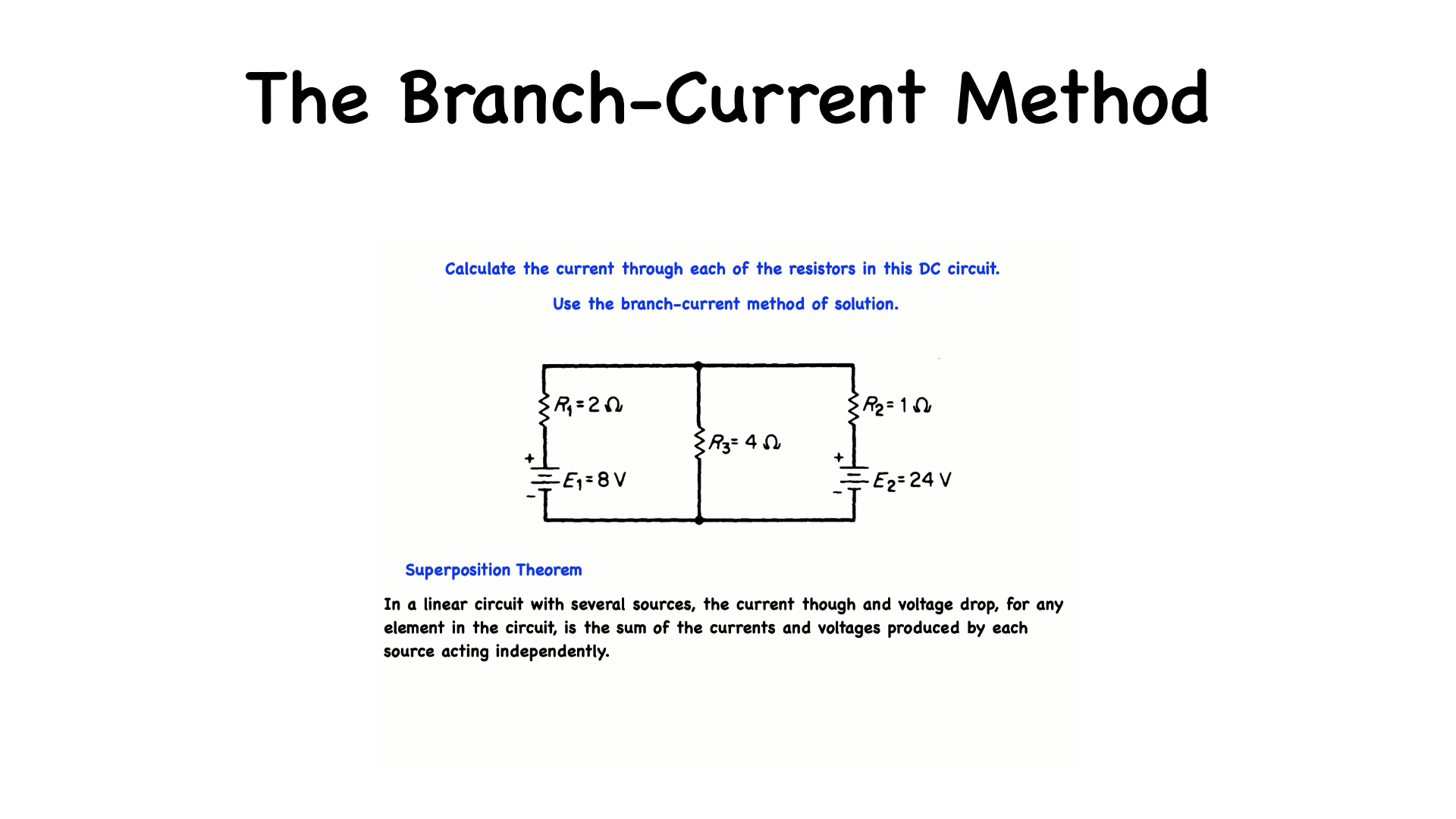
In this problem we are to calculate the current through each of the resistors in this DC circuit using the branch-current method of solution. The branch-current method makes use of the… Superposition Theorem, which states…”In a linear circuit with several sources, the current though and voltage drop, for any element in the circuit, is the sum of the currents and voltages produced by each source acting independently.”

To start…I am going to label all the nodes…There are four nodes in this circuit, as indicated by the letters Node A, Node B, Node C and, Node D.
Nodes are junctions where two or more current paths come together…
A branch is a portion of a circuit consisting of one or more elements in series. This circuit contains 2 sources and 3 branches, each branch of which is a current path in the network.
Branch ABC consists of the power supply E1 and R1 in series, branch ADC consists of the power supply E2 and R2 in series, and branch CA consists of R3 only. I am assigning a distinct current of arbitrary direction to each branch of the network.
I1, I2 & I3 these currents create voltage drops across each resistor. The polarities of which is determined by the assumed direction of current and the passive sign convention.
The polarity of the power-supply terminals is fixed and is therefore not dependent on the assumed direction of current.
Notice the words arbitrary and assumed direction… after the calculations are made if the assumed current is minus then the current will be flowing in the other direction to the assumed direction.

A closed loop is any continuous connection of branches, that allows us to trace a path, which leaves a point in one direction and returns to that same starting point…from another direction without leaving the network.
Now we apply Kerchof's Voltage Law around each closed loop…for loop ABCA or loop 1…remember Kerchof's Voltage Law tells us that…the algebraic sum of changes in potential around any closed circuit path or loop, must be zero…starting at node A voltage source E1 raises the potential to 8 volts therefore plus 8 and the resistors voltage change is - 2I1 for resistor R1 and - 4I3 for resistor R3. These voltage changes when added together must equal zero (KVL) so we write that in the form of an equation,… as you see here…the currents are the unknowns.
For loop ADCA…plus 24 for E2 and the resistors drop the voltage by - I2 for resistor R2 and - 4I3 for resistor R3. These voltage changes when added together must equal zero… we write that in the form of an equation plus 24 - I2 - 4I3 = 0. Kerchof's Current Law at node C tells us that I1 + I2 = I3.

The three equations now can be solved by the elimination method. Firstly, by rearranging the last equation, we can clearly see that we can express I3 in terms of I1 & I2.
➜ Now using the above two equations I'm going to substitute for I3 which is equal to I1 + I2.
We now have 2 equations with 2 unknowns…I1 & I2 The unknowns being the two loop currents…We could've gone immediately to these two equations to solve this problem however we introduced a 3rd equation and a 3rd unknown by using Kirchhoff current law…which as you recall generated…the KCL (bottom) equation this points out the fact that there are more than one way to solve or analyze a mesh equation…Solving for I1 & I2 will also give us I3 which is all just mathematics and I’ll leave that to you to solve as a mathematical exercise.
If you have made it this far and are indeed finished calculating the equations, coming up with the answers for the three current in this problem…you have demonstrated your interest in electrical systems. One of the systems that are out there in today's world is home automation. You can use your newly acquired knowledge to possibly proceed with automating your home.

If you are ready to elevate your living space with home automation, now’s the perfect time to transform your home into a smart, efficient household! In order to explore an incredible range of innovative products that cater to all your smart home needs.
Simply this website…https://tinyurl.com/thesmartesthouse
Don’t miss out on exclusive discounts available for a limited time! Take the first step towards a smarter home and discover how easy it is to enhance your lifestyle with cutting-edge technology. Your dream home awaits!

Remember, this video has been brought to you by PSPT, where you will find electrical train training videos when you go to this web address…https://bit.ly/47YB3vh...which will also give you a free copy of my 50 page crib sheets that you can use while viewing any of the courses or just keep handy during your every day work.
Blog #47 - Home Automation, Zooz Switches…There are Several to Choose From
/
As part of my home automation series, this will be the 3rd video on Zooz Switches… in fact there are several to choose from.
Eventually, I will be posting these videos on the subject in my Stan store at this web address…https://stan.store/GVB
Zooz Switches…There are Several to Choose From

The Zooz Series ON/OFF Switches include the:
ZEN71
ZEN72
ZEN76
ZEN77

and the ZEN30 A stacked 2-in-1 switch, used for example, controlling a fan motor and light separately.
ZEN32 which has 4 separate programmable buttons.

Here is a simplified overview of the recommended models for the most common scenarios. It is recommended that you refer to the detailed written guide for any special situations, like the using multiple Zooz switches in a 3-way or 4-way installation or non-conventional wiring scenarios. Always check the specifications of your switch model and electrical rating of the load or bulbs you want to use FIRST, making sure the Wattage is within your switch's electrical rating.
These units are best used for non-dimmable lights and other support loads

These recommendations are only for dimmable lights, do not use with receptacles

If you are ready to elevate your living space with home automation, now’s the perfect time to transform your home into a smart, efficient household! In order to explore an incredible range of innovative products that cater to all your smart home needs.
Simply this website…https://tinyurl.com/thesmartesthouse
Don’t miss out on exclusive discounts available for a limited time! Take the first step towards a smarter home and discover how easy it is to enhance your lifestyle with cutting-edge technology. Your dream home awaits!

Remember, this video has been brought to you by PSPT, where you will find electrical train training videos when you go to this web address…https://bit.ly/47YB3vh...which will also give you a free copy of my 50 page crib sheets that you can use while viewing any of the courses or just keep handy during your every day work.
Blog #46 - Using the Zooz ZEN71 as a Three-Way Switch
/
As part of my home automation series this will be the 2nd video on The Zooz ZEN71 Switch and using it as a three way switch.
Eventually I will be posting training videos on the subject in my Stan store at this web address…https://stan.store/GVB
A three-way switch is a type of electrical switch that allows you to control a single light or set of lights from two different locations. It is commonly used in hallways or large rooms where you want to turn the lights on or off from either end. In a three-way switch setup, two switches are connected to the same light fixture, enabling this dual control functionality.

Several wiring schemes can be used to connect 3 way lighting circuits depending on the location of the source in relation to the switches and lights. These wiring diagrams show typical connections to standard single pole double throw switches.

Now let's look at how we will connect a Zooz ZEN71 switch to this existing three way switch set up.
This is OPTION 1 (Load and line in the same box)
The diagrams show all connections but ground (the ground wire was excluded in order to simplify the illustrations).
This top diagram illustrates the connections using regular double pole single throw switches that you will be converting.
You'll usually see the power line in this box (a bundle of black wires if it's a double or triple box) and the black from your 14-3 romex will be connected to another black (most likely your lights) instead of being connected to the switch. This option can have a few variations depending on the creativity of the electrician who first wired the 3-way.
The bottom diagram illustrates the connections replacing the left-hand illustrated switch with a Zooz Z wave switch.
If you can't match the diagrams exactly The Zooz manufacturers are very responsive so contact them and they will provide you with assistance.
This is OPTION 2 - with the Load and line in separate boxes.
You'll usually see the black from your 14-3 romex connected directly to the switch on both sides.
This can also be wired using different parts of the 14-3 as traveler so if the diagrams almost match but not quite, don't experiment, contact the manufacturer first.

OPTION 3 (two point control of Zoos switches)
There are a few different scenarios that may match your set-up better but they all include a situation where the power line (also called power source or line) is located by the light and not in any of the switch boxes. This is bad news because Zooz switches need direct connection to power and neutral to work. If you can't bring power and neutral to one of the boxes, you won't be able to use Zooz or most other Z-Wave in-wall switches.
If you're unsure about the wiring process or are unable to match your wiring to the provided diagrams, don't proceed with the installation. Take images of your installation and reach out to the manufacturer if you have any questions or experience any issues.

If you are ready to elevate your living space with home automation, now’s the perfect time to transform your home into a smart, efficient household! In order to explore an incredible range of innovative products that cater to all your smart home needs.
Simply go to this website…https://tinyurl.com/thesmartesthouse
Don’t miss out on exclusive discounts available for a limited time! Take the first step towards a smarter home and discover how easy it is to enhance your lifestyle with cutting-edge technology. Your dream home awaits!
Remember, this video has been brought to you by PSPT, where you will find electrical train training videos when you go to this web address…https://bit.ly/47YB3vh...which will also give you a free copy of my 50 page crib sheets that you can use while viewing any of the courses or just keep handy during your every day work.
Blog #45 - The Zooz ZEN71 800 SeriesON/OFF Switch
/
As part of my home automation series this will be the first video on The Zooz ZEN71 Switch.
Eventually I will be posting training videos on the subject in my Stan store at this web address…https://stan.store/GVB

Introducing the Zooz ZEN71 800 Series On/Off Switch - more than just a simple light switch. While it works seamlessly as a standalone switch, this intelligent digital device becomes a powerful tool when paired with a compatible home automation hub.
Think of it as the brain behind your lighting control, capable of being programmed for endless possibilities: schedules, automations, and customized scenes to match your lifestyle. It's not just about turning lights on or off—it's about transforming your home into a smarter, more responsive environment.
This smart home device has several key features:
Z-Wave Long Range capability, extending wireless coverage up to 1 mile if the hub supports it.
It has the 800 series chip for improved range, faster signal, SmartStart inclusion, and S2 security.
It also has a direct 3-Way Solution.
The Compact profile at 1.1" deep, easily fits crowded or shallow boxes.
This switch has an adjustable LED indicator with customizable color and brightness.
Built-in range test tool for diagnosing network issues.
Scene control functionality on compatible hubs.
Smart bulb mode to disable the relay for wireless control or use as a remote.
Installation…
Before installing, make sure the load does not exceed 960W for incandescent lights, 150W for compact fluorescent lamps and LED's, or 1800W (15A) for resistive type loads. Check your wiring first to confirm that you have all the following wires present in your gang box: load (most often black), line (most often black), neutral (most often white), and ground (most often green).
Here are some helpful wiring tips:
Make sure the gang box you are about to install the switch has a neutral wire available - you will not be able to get the ZEN71 switch to work without a neutral wire.
Unlike regular mechanical switches, Z-Wave switches require all of the wires to be connected exactly as indicated - line and load wires can never be swapped as it sometimes happens to the most experienced electricians.

This is all for now stay tuned and return to this site as I take a deep dive into the various characteristics and settings for this sophisticated switch.

If you are ready to elevate your living space with home automation, now’s the perfect time to transform your home into a smart, efficient household! In order to explore an incredible range of innovative products that cater to all your smart home needs.
Simply this website…https://tinyurl.com/thesmartesthouse
Don’t miss out on exclusive discounts available for a limited time! Take the first step towards a smarter home and discover how easy it is to enhance your lifestyle with cutting-edge technology. Your dream home awaits!

Remember, this video has been brought to you by PSPT, where you will find electrical train training videos when you go to this web address…https://tinyurl.com/thesmartesthouse…ve you a free copy of my 50 page crib sheets that you can use while viewing any of the courses or just keep handy during your every day work.
Blog #44 - Another Practice Problem Using The Noton’s Theorem
/
As part of my problem series in this video, I will be Calculating Current Using Norton’s Theorem.
Once I am finished with this series of problems I will be posting them in my Stan store, at this web address…https://stan.store/GVB

Find I0 in this circuit using Norton’s Theorem
In this network, the 2kΩ resistor represents the load. In applying Norton’s Theorem we will replace the network without the load by a current source, the value of which is equal to the short-circuit current computed from this network, in parallel with the Norton equivalent resistance determined from. This bottom circuit.
with reference to the top circuit, all current emanating from the 12V source will go through the short-circuit. Likewise, all the current emanating from the 2mA current source will also go through the short-circuit so that IN = 12/3kΩ - 2 mA = 2mA
If this statement is not obvious to the reader, then consider the bottom circuit shown here…Knowing that the resistance of the short-circuit is zero, we can apply current division to find IN which ultimately is equal to I…indicating that all the current in this situation will go through the short-circuit and none of it will go through the resistor.
Going back to calculating RN, we find that the 3k and 6k Ohm resistors are in parallel and thus RN = 3k||6k = 2kΩ…Now the Norton equivalent circuit consists of the short-circuit current in parallel with the Norton equivalent resistance as shown by the bottom circuit.

Remember, at the terminals of the 2kΩ load, this network is equivalent to the original network with the load removed. Therefore, if we now connect the load to the Norton equivalent circuit as shown in here, the load current I0 can be calculated via current division as I0 = 2mA(2kΩ/(2kΩ + 2kΩ) = 1 mAmp

Hey there, tech enthusiasts and smart home aficionados!
I'm thrilled to announce that I'll be diving deep into the world of home automation in an exciting new series of blogs and social media posts. Get ready to transform your living space into a futuristic haven of convenience and efficiency!
In the coming weeks, I'll be sharing my insights, reviews, and tips on the latest smart home gadgets and systems. We'll explore cutting-edge products that will revolutionize the way you interact with your home, from AI-powered assistants to energy-saving devices and advanced security solutions.

If you are ready to elevate your living space with home automation, now’s the perfect time to transform your home into a smart, efficient household! In order to explore an incredible range of innovative products that cater to all your smart home needs.
Simply this website…https://tinyurl.com/thesmartesthouse
Don’t miss out on exclusive discounts available for a limited time! Take the first step towards a smarter home and discover how easy it is to enhance your lifestyle with cutting-edge technology. Your dream home awaits!

Remember, this video has been brought to you by PSPT, where you will find electrical train training videos when you go to this web address…https://tinyurl.com/thesmartesthouse…which will also give you a free copy of my 50 page crib sheets that you can use while viewing any of the courses or just keep handy during your every day work.
Blog #43 - The Z-Box Home Automation Hub
/
In this video we are going to look at The Z-Box Hub: The Future of Smart Home Automation
Welcome to the world of advanced home automation with the Z-Box Hub: S2 700 Series Z-Wave Plus Smart Home Hub. This innovative device is the result of a powerful collaboration between Zooz and Fibaro, two leaders in Z-Wave technology. The Z-Box Hub represents the pinnacle of smart home control, offering unparalleled compatibility, security, and user-friendly features that will transform the way you interact with your living space.

The Z-Box Hub is built on the latest 700 series Z-Wave library, ensuring compatibility with a vast array of certified Z-Wave products. It offers local access to your smart home, keeping your devices and scenes private without any contracts or fees. The hub's intuitive scene creator allows for both simple rules and complex multi-conditional scripts, giving you unprecedented control over your home automation. Security is a top priority, with the implementation of the S2 Authenticated protocol and SmartStart for a safe and reliable mesh network.

The built-in do-it-yourself alarm panel tool with a PIN pad adds an extra layer of home security.

The Z-Box Hub offers multiple connection points for ultimate flexibility. It can connect to your home network via Wi-Fi or through an optional Ethernet adapter for a LAN connection. The hub's interface is accessible through any web browser on your local network, allowing for easy setup and programming. For voice control enthusiasts, the Z-Box Hub can be linked to Alexa or Google Home using the FIBARO Smart Home integration. This enables voice commands for your Z-Wave devices and bridges them with other smart home technologies available through your smart speaker. The hub also features OTA (Over-the-air) firmware update capabilities and easy association creation for your Z-Wave products.

The Z-Box Hub's compatibility extends far beyond basic Z-Wave devices. Through third-party integrations from the FIBARO marketplace, you can connect your hub with popular smart home ecosystems like:
Sonos speakers,
Philips Hue bulbs, and
Samsung TVs.
For the tech-savvy users, the Z-Box Hub provides a built-in Quick App tool for creating custom integrations and virtual devices. Additionally, the full local API documentation is available directly from the web User Interface, allowing for connections with other systems. This expansive compatibility ensures that your Z-Box Hub can grow and adapt to your changing smart home needs.

The Z-Box Hub is more than just a smart home controller… it's a gateway to the future of home automation. With its advanced features, robust security, and extensive compatibility, it provides a solid foundation for your smart home that can evolve with your needs. Whether you're a smart home novice or a seasoned enthusiast, the Z-Box Hub offers the tools and flexibility to create the perfect automated environment. Experience the power of true inter-operability and take control of your smart home like never before with the Z-Box Hub: S2 700 Series.

Don't Miss Out on Smart Home Success!
Be Ready to take your home automation game to the next level.
This web address…https://bit.ly/Z-Box_Hub…will provide you with direct access to a YouTube channel for an exclusive look at Home automation hubs that will revolutionize your smart home setup. At this web address you'll also be asked for your email address which will not be shared or distributed in anyway, but it will allow me to keep in touch and let you know of any additions or updated information. This YouTube channel will provide you with information on five Z-Wave Hubs.
• ZST39 800 Series Z-Wave Long Range S2 USB Stick
• ZST10 700 Series Z-Wave S2 USB Stick
• USB-A 3.0 Extension Cable (3 meters)