Blog #13 - House Wiring Diagrams

A wiring diagram is a pictorial representation of an electric circuit, where the elements of the connections, between devices, and the power source are shown in the conventional methods as simplified shapes. A house wiring diagram is thus, a wiring diagram of a house.

This diagram can be a wiring diagram, for any electric circuit in your home, which is drawn mostly so that it can easily guide the electrician (or yourself) when needed. The diagram consists of connections between elements of the circuit, and their relations, to and from the power source.

It takes into account, the dimensions of the room, and the input and output points, keeping in mind the access to those points.

House wiring diagrams are the visual representation, or design of the entire electrical wiring system, or circuitry of a house (or a room) that helps in creating the system to distribute energy that can be used to power the various equipment and appliances around the house. It will aid in the proper installation and operation of the different elements, included in the design, such as electrical outlets, the meter base, switches and breakers and more.

In this blog, we will talk about the various aspects of a basic house wiring diagram. We will understand what it is, why we need it, what benefits we can gain from it as well as the principles and symbols involved in the whole process. Finally, we will look at some examples, and see how we can draw a house wiring diagram.

The above house wiring drawing is what I would call, the minimum requirement. It shows switches, and electrical outlets, (lights and receptacles). It indicates where and how the lights are controlled, and from which switches, but leaves the details of how they are connected, to the electrical contractor. As you will see in the following information, details can be added, for example where the feed wires go, and the circuits that are connected to the various feeds.


All of the drawings in this blog were constructed using the software EDraw Max. EDraw Max.anrdoezrs.net/click-100680115-14099230 is the best diagram solution to help you design, create, improve, and achieve your goals. It’s an all-in-one graphics software that makes it simple to create floor plans and electrical diagrams.

Find on the E-Draw Max link

There can be no question as to the importance of a House Wiring Diagram. But still, we must address the need for using one. It is a vital part of wiring a house. The reasons are as follows:

Financial: An electrician can only estimate the amount of wiring needed to set up the electrical system. The house wiring diagram, on the other hand, can give the exact value. Say your electrician does not use a house wiring diagram, this can lead to severe inefficiencies. There can be two possible scenarios: 

  1. Without an exact amount, your electrician may end up using more wiring, which can lead to wastage and excess installation, which leads to cost overruns.

  2. The opposite can also happen, less wiring would mean spending time buying the remaining wiring which leads to delays and ineffective costing.

Timescale: Not only finance, but also the timeframe of the work gets affected. Without an adequate amount of wiring, you will need to buy more or wait for the new installation to be delivered. It can hamper the timeframe and coordination of the work, especially on big projects, like that of an apartment building, or a condominium.

Safety: Whenever working with electrical systems, we are all taught to look out for safety. Injuries can happen anywhere, anytime, and due to many reasons. A useful house wiring diagram can show where the points of danger lie in the whole network. It can help to avoid hazards, open hot wires, and many other such scenarios. An injury would mean time delays as well as an expensive hospital bill. A House Wiring Diagram thus also serves as a tool for avoiding mishaps.

Wiring diagrams use an array of special symbols that represent various circuit elements, like switches, bulbs, electric outlets, breakers, smoke detectors, and many more. This table lists the most common symbols along with their names. Other than these symbols, there are some lighting, electrical and telecom, and wall, shell or structure symbols that are involved in a house wiring diagram. In fact, there is a plethora of symbols, that are currently in use and new ones constantly being introduced to the mix. However, they are usually self-explanatory, especially when a lot of them, will come with side text, that further explains the symbol.

To start with, let's look at the details that can be added to the bedroom wiring, starting with bedroom number one. 

Locating the power panel in the garage, the first feed wire will be connected to the two-ganged switch box in this bedroom next to the door. One switch will control the ceiling light, and the Second switch will control the tops of the duplex plugs in the bedroom. Looking at the next two bedrooms, a second Circuit will bring power to these rooms, starting at the closest duplex plug of bedroom three.

The power will then extend to the two adjoining duplex plugs, as well as bringing power to the bedroom light switch, which controls the overhead light in this bedroom. Because we want to continue the power feed to the light independent of the light switch, we will connect the switch to the bedroom overhead light with a #14-3 Cable wire. This will allow us to drop the feed to the fourth duplex plug in the bedroom.

We will carry on this circuit into bedroom number two, to the closest duplex plug, and then to the overhead light in the bedroom which is switched from a position next to the entrance door. The circuit is also extended to the other two duplex plugs in the bedroom.

The light in the closet is being fed from the overhead light in the bedroom. Because the closet light is a pull-chain, it does not require a wall switch, moreover, we can finally feed the last duplex plug in the bedroom from the closet light as shown.

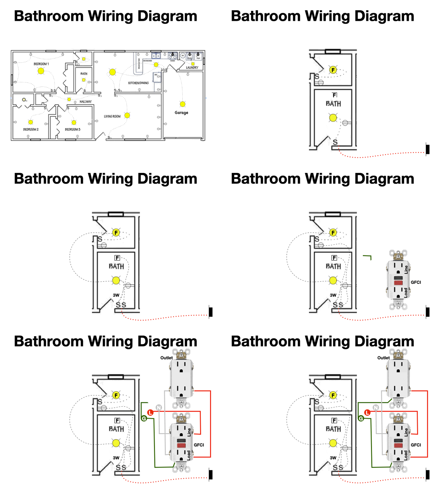
We are now going to look at the bathroom wiring in more detail…A third feeder wire is brought in from the power panel in the garage, and connected to the switch box in the main bathroom.

We want to add exhaust fans in both bathrooms. For the small bathroom, it will be in the light fixture and will come on with the light. But in the main bathroom, we want a separate fan controlled independently from a second switch.

We will use a #14 three cable from the switch to the main bathroom light in order to carry on a power feed to the smaller bathroom.

Power is fed from the two gang switch box to the duplex outlet receptacles in the bathrooms. The duplex plug in the main bathroom is a GFCI, (Ground Fault Circuit Interruptor) receptacle, which is a code requirement. The receptacle in the smaller bathroom is not required to be a GFCI if it is fed from the load side of the main bathroom receptacle as shown.

Let’s unscramble the confusion surrounding the kitchen lights, which are two lights, each controlled by a set of three-way switches. We are going to feed these light circuits at the three gang switch receptacle next to the garage door, picking up one of the garage duplex receptacles along the way.

Let's look at how a three-way switch schematically controls a light. Switch #2 is being fed with power, from a hot wire connected to its common terminal. Switch number 1’s common terminal is connected to the hot terminal of the light, Neutral is connected to the neutral terminal of the light and the carrier terminals of the switches are connected in parallel.


A three-way switch is a single pole, double throw type of switch which looks like this, schematically. I am going to color code the wires red that are electrically hot, or at 120 volts, for various positions of the switches. With the switches in this position, the red wires` are the wires that are hot. As you can see, the light is off.


Toggling switch #1, carries 120 volts all the way to the light. The light is now on.


When switch #2 is Toggled, the hot circuit to the light is interrupted, and the light once again is off.


Toggling switch #1, again completes the circuit to the light. The light is once again on.

I have maintained the same connections as the schematic drawing, but this time I am placing the components, the two three-way switches and the light, in separate electrical boxes, as in real life. The electrical box boundaries are indicated by the blue dotted rectangles. The feed wire is the #14-2, NMD cable, entering switch box #2 on the right. A #14-3, NMD Cable, is connected between switch box #1 and switch box #2. The white wire of this cable is not connected to either of the switches, but jumpers the neutral from the feed wire, through to the light. The red and black wires of this #14-3 cable, are connected to the carrier terminals of each switch. It does not matter, which carrier terminal is connected to which wire. Finally, a #14-2 cable carries the neutral and the switched hot wire, from switch box #2 to the light. Replacing the actual switches, the set up will look more realistic.

Now that we have the three-way lights figured out. Let's complete this one circuit by picking up the last outlet in the dining room area, and the refrigerator circuit by bringing the feed from that circuit over to the innermost receptacle in the garage, and then continuing on to feed the switch, which ultimately lights the laundry room area.

The last remaining outlet in the dining room area, will be on a separate feed, for no other reason other than we have lots of available circuits.

The next two feeder circuits will be brought out on #12-2 wire that is going to be fused with a 20 amp AFCI breaker, or an Arc Fault Circuit Interrupter breaker.

The dishwasher is going to be fed with a #14-2 cable, and a separate, 15 amp standard breaker. Next, we have to connect the washer and dryer. The dryer load will require a #10-3 feeder cable, and a 30 Amp, double pole breaker. The washer will only require a #14-2 feeder cable, and a 15 Amp single pole breaker.

The Range load will require a #8-3 feeder cable, and a 40 Amp double pole breaker.

Finally, the last outlet plug in the garage will be fed from a separate breaker rated at 15 amp.

All of these drawings were constructed using the software EDraw Max. EDraw Max is the best diagram solution to help you design, create, improve, and achieve your goals. It’s an all-in-one graphics software that makes it simple to create professional-looking graphics. For this blog, I used a combination of floor plans and Electrical diagrams.