Blog #11 - Basic Rules & Formulas

This blog is designed to give, the “do-it-yourselfer”, an introduction to the low-voltage electrical wiring found in residential homes. Most of it applies to any installation that uses a 120/240 AC volt supply. Of course, there are numerous permutations and combinations involved, but this blog will explain the most used, and generally familiar to the public. It is designed around the National Electric Code, (NEC) but codes vary, depending on where you are in North America, and indeed, the world. As a disclaimer, I am going to say that some of the wiring and some of the statements may not apply to local electrical codes. In order to be sure, the reader should check with the local authorities first, prior to changing any wiring in their homes. At the very least, this blog will provide a starting point for the aspiring student.

Reviewing the Basic Rules of Electricity, I am going to start with direct current circuits, and then very quickly move to AC circuits which are the type that is found in residential homes. All direct current electrical elements form electric circuits, and current will flow from positive to negative in a circular fashion around a loop. All electric circuits have Voltage, Current and Resistance (For the present time we are going to consider only resistive loads for simplicity). These three quantities are related by Ohm's law. which states that the current in a circuit will very, directly as the voltage and inversely as the resistance in the circuit. 

In this illustration, current will flow in a circuit formed by the wires connecting the battery through the lightbulb back to the battery. The voltage of the source equals the voltage drop across the lightbulb in this case and let's say, it was 120 Volts.

Of course, batteries don't operate household systems. It is AC current, which is changing polarities, 60 times a second. This illustration is showing what a lightbulb might look like if the polarities were changing at 1.6 times a second. As you can see, the oscillations are very visible. A fact which is not at all acceptable.

Now, if we speed up the AC source to 60 cycles a second, the filament in the lightbulb does not get a chance to cool in between the cycle changes, hence the light looks like it's on steady. which indeed it is. The use of AC is mainly because it allows for voltage transformation. That is, to be stepped up, and transferred over long distances, and then, stepped down, to lower levels, to make it useful, and safe within homes.

The book is one of a kind in that it teaches the concepts of basic electricity in a way that is clear, concise, and very easy to understand. It forms an excellent foundation for those who wish to proceed from the basics to more advanced topics.

Numerous illustrations are included to simplify learning both theories and their applications. Direct-current and alternating-current devices and circuits are explained in detail. Magnetism, as well as motors and generators are

Let’s have a closer look at this changing polarity of 60 times a second. If we plot the voltage over time. one and a half seconds, you can see that it starts at “0”. rises to a maximum, then reduces back to “0”, and proceeds to a negative maximum. then goes back to “0” again. It repeats itself every one-sixtieth of a second. It does this in what is called a “sinusoidal” shape…as you see here.

For simplicity, we will assume that most loads are resistive in homes. (lightbulbs, baseboards, electric heaters, electric stoves, ovens, etc.). Therefore, the instantaneous current, in the circuit (shown here in red) will follow the voltage, and it too will be “sinusoidal” in shape. We say that the current is “in-phase “ with the voltage.

The question now becomes. How do we describe this sinusoidal voltage and current, if it is continuously changing? There are several ways.

We can measure and compare the amplitude or peak, as you see here. Another way is to measure and compare the peak to peak…. still, another way is to average the curve, but that would just be “0”. not too useful, unless we squared the value first, then found the square root. This would essentially change the shape of the curve, to look like all positive going curves above the zero line.

Now, we could average the value of this voltage, or current, and it would be a positive value, and greater than “0”. This value is known as the “Root-Mean-Square”, or RMS value of the voltage and current. It is exactly the square root of 2. or 0.707 times the peak value.

This averaging is the equivalent of shaving off the peaks of the curve above the RMS line, which would exactly fill the space between the curves below the RMS line.

This may seem like a bit of mathematical manipulation, however as it turns out, it is very useful in calculating the average power, and energy. And as a matter of fact, all AC current and voltages are measured in RMS values and all meters, voltmeters, ammeters, and multi-meters, unless otherwise stated, are registered in RMS values.

If you have a closer look at the RMS quality of the voltage over time, it is exactly what the DC voltage would look like, and in fact, RMS values are often referred to as the DC equivalent of AC voltage and current.

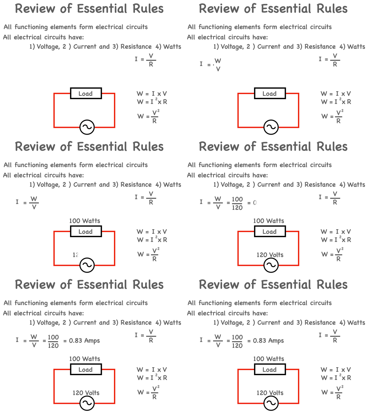
As I said, RMS values of current and voltages are used in calculating the average power, and energy. The power draw that a load, such as a lightbulb takes from the circuit, is expressed in watts. A load’s power rating is usually marked on the device, such as a lightbulb, and in this case, it is a 100 Watt bulb.

The power in watts consumed by a load is given by the current x voltage (using RMS values) or W = I x V where I is the current through the load, and voltage is the measured voltage drop across the load. Because the current in a circuit is equal to the voltage divided by the resistance we can rewrite the equation for watts, in either of the following two ways.

1) Watts = Current Squared times Voltage

2) Watts = Voltage Squared divided by the Load Resistance

As a final note, the standard symbol for an AC generator is not a two-ended battery, but a simple circle with a sinusoidal wave-shape in the middle.

Quite often, we have to calculate the current that a specific load will draw, given its rating in watts and we know the connected voltage. In that case, we will use the first equation re-written as…the current equals the rating in watts divided by the applied voltage. For example, if the load were a 100 watt incandescent light bulb and we know that the connected voltage is 120 Volts. Then the connected current is, 100 divided by 120 or 0.83 Amps.

Now if the load were not a 100 watt incandescent light bulb, but a 1 kilowatt heater. Then the connected current is 1000 divided by 120 or 8.33 Amps

Keeping the load of a 1 kilowatt heater changing its voltage rating and the connected voltage to 240 Volt. Then the connected current is, 1000 divided by 240. Which will drop the current to 4.17 Amps. At first glance, this might seem contradictive, in that we doubled the voltage, and you would think that we would double the current. however, the 1000 watt heater would have to be rated at 240 Volts. That is to say, that the load will consume 1000 Watts when connected to 240 Volts. Therefore, the connected current is given by, the rated power, 1000, divided by, the rated voltage 240.

Generally speaking, any AC circuit is made up of an AC Source. and load, usually a resistive load, which causes a current to flow. For example, let's say the voltage is 110 volts, and the load is 11 ohms. Ohm’s law tells us that the magnitude of the current is V divided by R or 110 divided by 11. Which equals 10 Amps. The power consumption can now be calculated 3 ways:

1) Voltage times the current…10 times 110 or 1100 Watts.

2) Current squared times the resistance or 100 times 11. Which is 1100 Watts.

3) Voltage square divided by the resistance. Which is 12,100 divided by 11 or 1100 Watts.

So far we have been dealing only with resistive loads. Which works the same for DC as well as AC power. However, there are 3 major types of linear loads, resistors, inductors, and capacitors. When dealing with capacitive and inductive loads, we have to be aware of the phase shift of the current that is introduced. Without going into details when dealing with these types of loads we have to look at the load as impedance, which will shift the current from the voltage, depending on the type of impedance, (capacitive or inductive). Also, we have to be certain that we are using RMS values for these loads, current, and voltage. In most cases we are not concerned about the phase shift when doing low-voltage wiring, however, we should be aware that some loads may cause the current to phase shift. 

In order to understand some of the wiring techniques, we should first have a peek inside the main breaker panel. Power from the utility enters in the form of two hot wires, and one neutral, arriving into the breaker panel. The neutral is connected to a neutral busbar. This bus bar contains several screws that can receive outgoing neutral connections. One of the hot connections is connected to a hot bus bar, let's call it “A”. The voltage of this bus bar is 120 Volts RMS, with respect to the neutral. The outgoing current limiting devices, (breakers), are connected here.

The other hot connection is connected to a second hot bus bar, let's call it “B”. The voltage of this bus bar is also120 Volts RMS with respect to the neutral. The case of the main breaker panel is grounded, and these ground connections are connected to a ground bus bar. This bus bar contains several screws, that can receive outgoing ground connections.

Inside this breaker panel, the ground bus bar is connected to the neutral busbar. This is called “bonding”. Bonding is the process of joining metal enclosures, equipment, raceways, metal water piping, gas piping, structural steel, and the like, together. Bonding items together, and connecting the bonded items to an equipment grounding conductor, places everything at the same potential, in this case, the neutral, and ensures an effective ground-fault current path, in the event of a ground fault occurring in an electrical system circuit. A Bonding Bar ensures that the neutral is at ground potential.

Lastly, there are two metal tracks that will hold one end of the breaker, the other end snaps and connects to the “hot”  bus bar.

This is a more realistic picture of a power panel, using breakers. I've indicated where the hot leads and neutral are coming from, ultimately the utility. There is a couple of things to note with this power panel. 

There is no main breaker, which probably means, this is a sub-panel being fed from the main breaker panel, and because the neutral lead from the utility is connected to only one neutral bus bar, in this example, on the right-hand side, there is a jumper, to connect it to the bus bar on the left hand side of the panel. This is usually a built-in connection of the power panel. 

Looking at the incoming connections from the utility and measuring the voltages over time. Remember, voltage is a measurement of the potential difference between two points. Let’s measure that voltage, between the hot terminal “A” with respect to the neutral. As you see, it rises to a maximum of 120 Volts positive, then returns to zero and goes to -120 Volts and back to zero and repeats itself. It will do this 60 times a second.

Let’s repeat the measurement, this time, of the hot terminal “B", with respect to the neutral. As you see it goes to a maximum of -120 Volts and back to zero and repeats itself. It also will do this 60 times a second.

Quite evident, is the fact that the voltages are out of phase with each other. In fact, they are 180° out of phase with each other. That means, if we take the measure of the potential difference between the two hot terminals, “A” and “B”, the result would look like the red plotted sinusoidal curve.

This is the potential difference between the two hot terminals “A” and “B”, with respect to each other. As you see, it rises to a maximum of 240 Volts positive, then returns to zero and goes to -240 Volts and back to zero. and repeats itself and will do this 60 times a second.

 Low voltage wiring will involve the requirement of different sizes or gauges of wire, depending on the load that it feeds, or more precisely, the amperage it will have to carry. Wire sizes are categorized by what is known in North America, as the American Wire Gauge, (AWG). This is a  measure of wire thickness, (which also dictates the cross-sectional area, and for a given material, ampacity). For example. 14 AWG wire, has a nominal diameter of 0.0641in, or 1.62814 mm. Note here, that steel wire is measured by a different gauge. AWG only applies to wire used to conduct electricity.

These two charts describe the characteristics and capabilities, of the various wire gauges of copper wire. The chart on the left is the current caring capacity of the various copper conductors. for example, for a load that draws 15 amps, #14 AWG wire is required. The chart on the right, along with describing the diameter, indicates the resistance of the wire in ohms per foot. This is significant for long runs of cables.

When wiring a house, there are many types of wire to choose from, some copper, others aluminum, some rated for outdoors, and others indoors.  In general, however, there are only a couple of varieties used for wiring a residential home.

Romex, (shown here in yellow), is the trade name for a type of electrical conductor with non-metallic sheathing, that is commonly used as residential branch wiring. In fact, Romex will be the most common cable you'll use in wiring a house.

NM, NMD, NMB and NMC conductors, are composed of two or more insulated conductors contained in a non-metallic sheath. The coating on NMC cable is non-conducting, flame-resistant and moisture-resistant. Unlike other cables commonly found in homes, they are permitted in damp environments, such as basements.

Underground feeder conductors appear similar to NM cables, except that UF cables, contain a solid plastic core and cannot be “rolled” between fingers.

Romex is used for most lighting and outlet circuits in your home.  Romex will be labeled with, for example, “14-2" or "12-3".  The first number indicates the gauge of the wire.  Your choices are typically 10, 12, or 14 gauge.  The second number indicates the number of conductors (excluding the ground wire excluding the ground wire). A 12-2 Romex will have a black, (hot) and a white (neutral) wire as well as an unsheathed copper wire for ground.  A 12-3 Romex, will have a black (hot), a red, (hot), a white, (neutral), and bare copper. 

Finally, a couple of comments in regard to wiring diagrams and house plans. Home electrical wiring diagrams should reflect code requirements, which help you enjoy lower energy bills when you implement energy efficiency into the electrical project design.

A typical set of house plans shows the electrical symbols that have been located on the floor plan but do not provide any wiring details. It is up to the electrician, to examine the total electrical requirements of the home, especially where specific devices are to be located in each area and then decide how to plan the circuits. The installation of the electrical wiring will depend on the type of structure, and construction methods being used. For example, a stick frame home, consisting of standard wood framing, will be wired differently then say, a log home, because of access restrictions.